


 Reply With Quote
Amazing work, thank you very much. You resume some advanced technics for newbies like me.
Kindest regards, Sergio Kauffman.

 Forum Guy

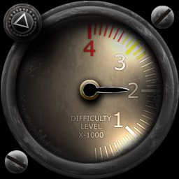
I began this trying to cover step by step how I've built gauges in the past, but there as too many steps. So, I've decided to just make a sample gauge, and then provide the PSD's showing how it's done. These PSD's are pretty good teachers by themselves I think.
Download the PSD's used in this tutorial:
gauges.zip
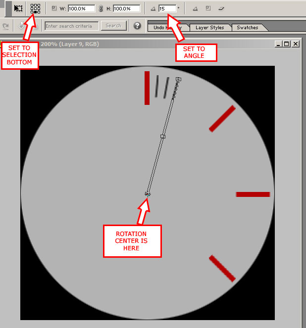
To provide more info on the making of the gauge face tick marks, I'll write up some tips and include an example of how I use Photoshop Elements' "Transform" tool (Control+T) for this process.
Firstly, You'll see in my PSD for the gauge face that I've got a layer called "Base Large" and Base Small" ticks. These are the elements that formt the tick marks on the gauges face, and all others are copied from these which are NOT rotated so that I have spares. If you check the center of these layers, you'll find a pixel, which is right near the center of the image area, in this case 128,128 of the 256,256 image. These are reference marks for when I rotate marks.
For the rotation, I select the tick mark AND the center pixel together. Then use the Transform tool, and center the rotation point around the lower part of the selection, where the pixel is. In reality, this pixel, keeps the transform tool's handles area right to the center for easily keeping the rotation centered to the gauge.
So, how far to rotate the tick marks? Some basic math works here:
For full cirle gauges like altimeters:
360 (degrees in full circle)/Number of needed markers
So 24 markers around a full circle would be:
360/24= 15 degrees rotation per marker.
For partial circle gauges like RPM:
Degrees covered by marks/Number of needed markers
So 24 markers around a half circle would be:
180/24= 7.5 degrees rotation per marker.
So say we type 7.5 degrees into the transform rotation area, and are ready for the next marker. Just add the next marker's rotation amount to the previously added markers and that's where it belongs from straight up. After creating 5 or so markers, you can repeat this process but copy and rotate groups of markers together (I merged the separate markers into one layer which I then copied). This is a big time saver when lots of markers are needed.
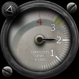
Next, you'll find a layer called "Small ticks merged colors". This layer is the merged result of my work above. They were all black when I built them, but I wanted color and so simply enabled "preserve transparency" and painted them the colors I wanted, they are very easy to work with this way. Same for the larger tick marks. Of course, when the ticks are done, I erased the central pixel so the gauge center was clear.
On the bezel PSD, it's alot like creating an aircraft skin, which can't be described in a short way. Use your skinning skills, and examine my layers to see how I build up my effects.
In the final product, I'd choose my options based on application. For 2D art, including the "glass reflections" layer adds some realism. This is doable in FS2004, but with some difficulty and limitations. If I coded the FS2004 XML gauge to use a night light when the panel lights are on, I could reference the "night light card" image from the XML for that effect, which is better than the MS default night illumination.
Hope this helps!
-adlabs6
Last edited by adlabs6; 11th December 2015 at 06:23.
Junior Member
Amazing work, thank you very much. You resume some advanced technics for newbies like me.
Kindest regards, Sergio Kauffman.
Member
Do you have any video version of this tutorial?
 Posting Permissions

