-
AMT Shelby GT350 build
My next (current) project:
My model locomotive project has shown just how inexperienced I am at painting models with the airbrush. The paint job on the train will work, but it's not by anything but luck.
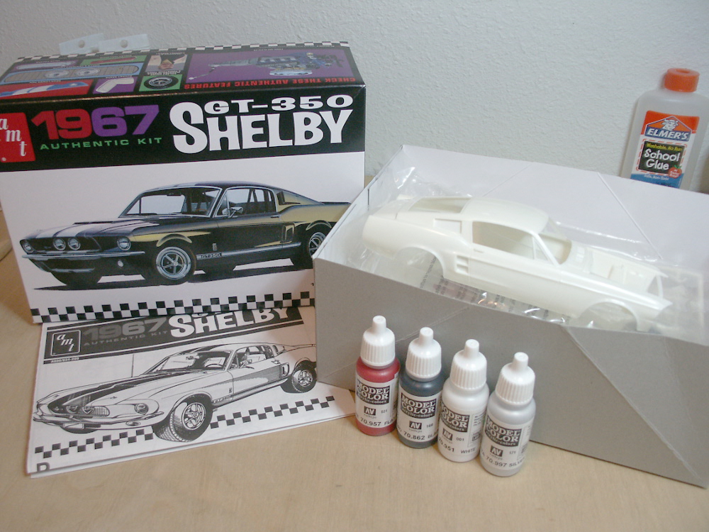
To remedy this, I'm going to start a new kit and learn and improve as I go. After standing around looking at kits in the hobby shop too long, I chose the Shelby GT350 by AMT. This kit has the full frame components modeled, rather than the simple metal axle some of the AMT re-releases have. As fun as some of the gassers looked, the extra detail in this kit should provide many more opportunities for painting and detailing experience.
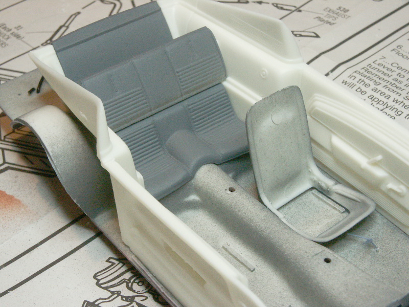
Besides, I've said it before (as have many others). Back when I last built a model kit 20 years ago, I didn't have an airbrush. Well now I do... it would be a shame to never build a kit now!  To do the job right, I've bought some Vallejo Model Color airbrush paints. Red, White, Black Grey, and Silver. These along with my Badger airbrush paints should get me anywhere I'll need to go with this kit. The body will be red with white stripes, the interior parchment and black.
There aren't any specific photo etch or detailing aftermarket kits for this model, so it'll be pretty much built out of the box. Maybe a few scratch detailing parts from styrene, and some engine wiring details will be added. First thing is having to dechrome the plated plastic. As typical with these kits, the sprues join to the parts such that there will be holes, so I'll just dechrome the entire part tree and then use the silver paint to make all of it match.
-
10th March 2014, 01:30
#2
Re: AMT Shelby GT350 build
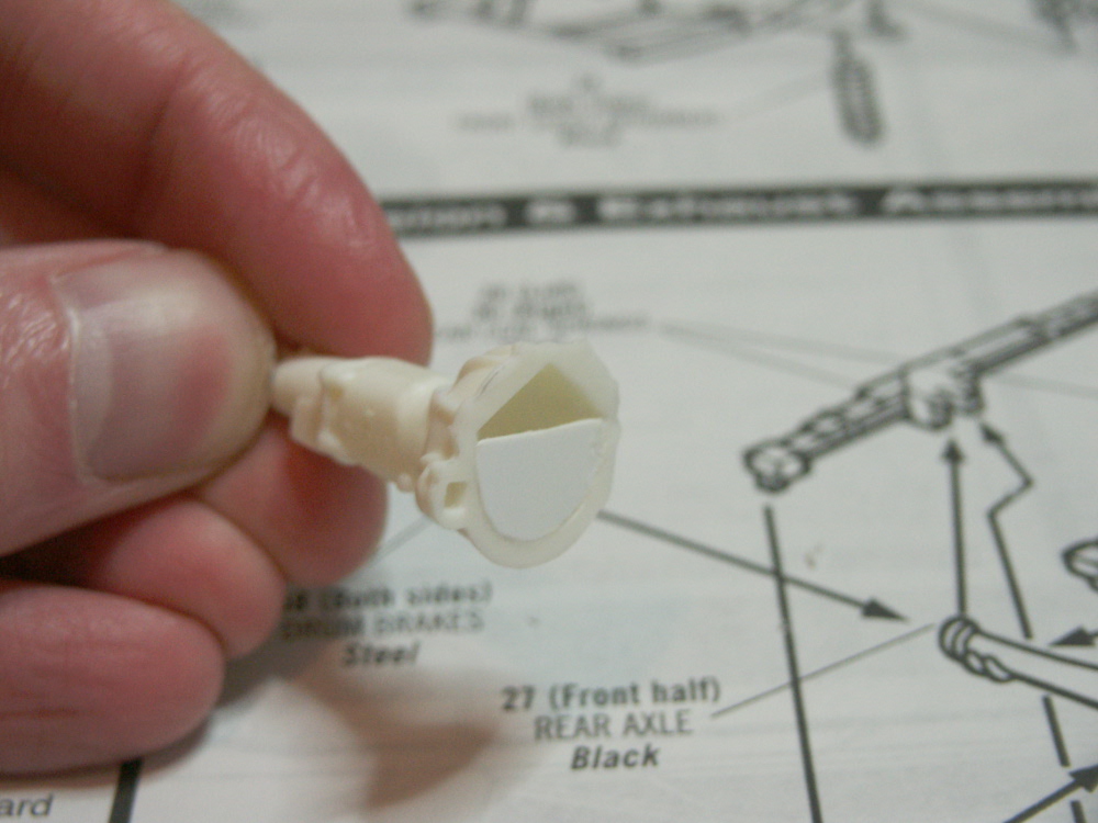
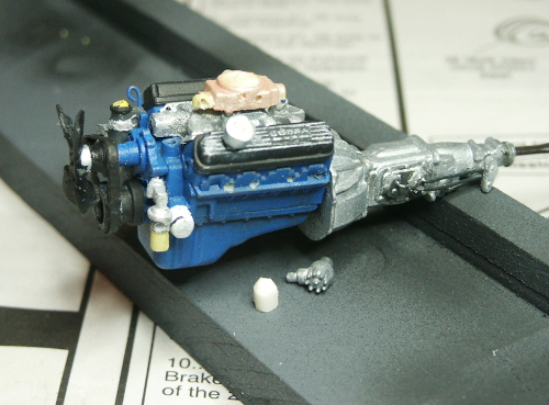
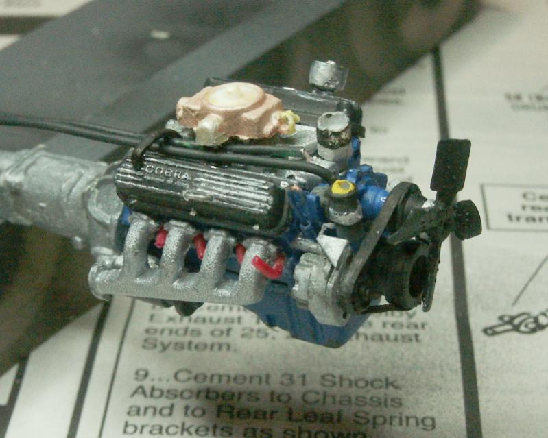
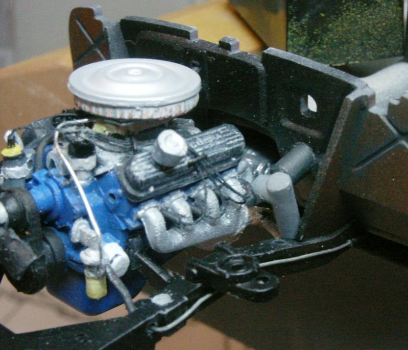
Some progress this weekend. First the early assembly of the engine. The engine block parts fit well, but the transmission halves didn't want to close tight. The big problem was the intersection of the transmission and engine left some huge gaps all around the face of the bell housing, which would have been visible when examining the underside of the model.
I considered filling this gap with putty, but this would have mean some masking when airbrushing the block and transmission colors. Instead, I cut away all the offending elements from the engine block parts, and filled in the opening on the bell housing with sheet styrene. You can see the wire oil dip stick I made glued in place, too.
Next, apparently there was no molding of the oil filter on the engine. My reference photos show it there, but nothing on the model anywhere. So I sculpted an oil filter from Milliput, also used some Milliput as filler on the transmission fix and to help close the gaps along the transmission halves.
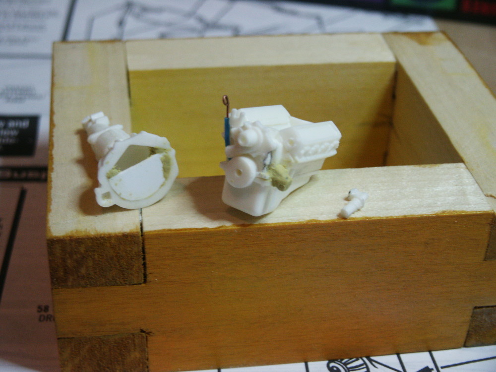
I also took the time to cut the fuel pump free of the water pump molding, just for easier painting.
And I did work on removing the plating. Most of the job was done in moments with regular bleach, but one side was apparently (and only partially) sprayed with a protective coating. So hit and miss removal on one side, but easy enough to continue here.
-
16th March 2014, 06:13
#3
-
17th March 2014, 05:19
#4
Re: AMT Shelby GT350 build
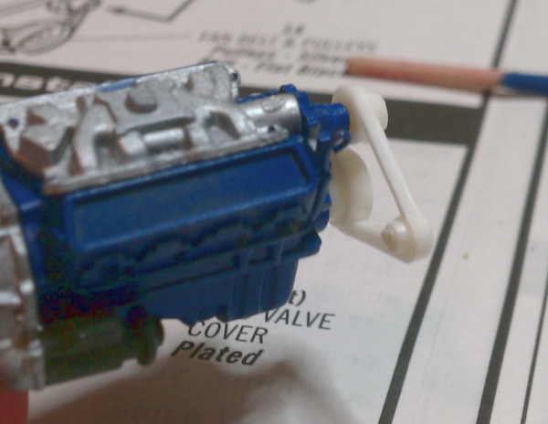
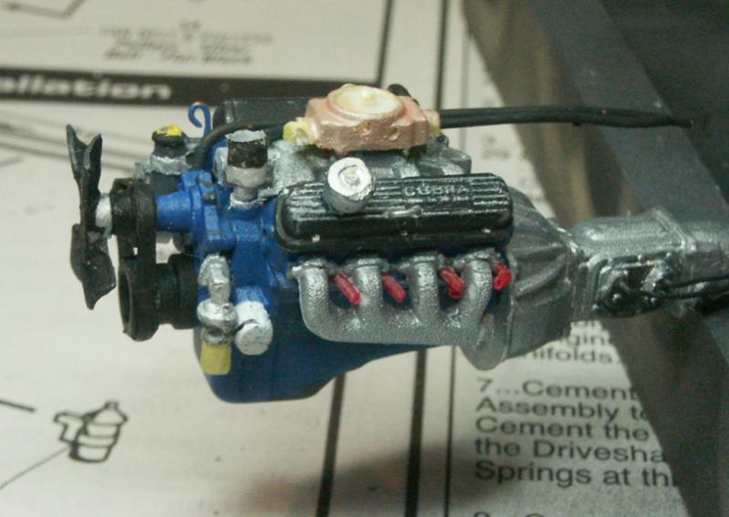
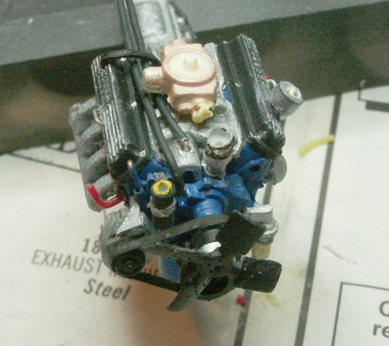
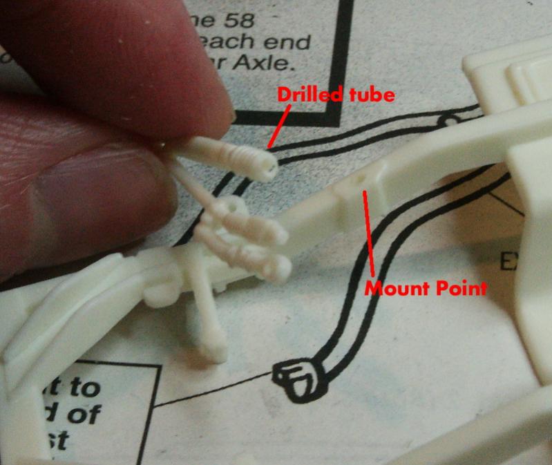
Another bit of progress. Valve covers are dechomed and painted. I had to build the oil fill cap from Milliput and painted silver, as there was nothing but a little dot molded there on the stock molding. You can also see the hole drilled in the side of the carb to hold the vent line from the oil fill cap.
The wire shift levers are shown, too. I cut off all the plastic rods, keeping only the levers which I drilled to accept the wire rods.
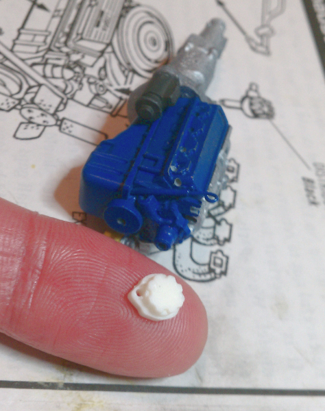
Also shown in this pic is the included distributor, and the new one I am building from scrap sprue. My ignition wiring won't fit comfortably on that stock part, so the replacement is drilled for better fit. I will try to show this better (and with a bit more completed I hope) in my next update.
And yes, the engine and table has a bit of white dust on it. Too much drilling tiny holes in styrene.
-
21st March 2014, 06:26
#5
Re: AMT Shelby GT350 build
Nice looking motor build! And I have to say WOW, that's an old kit! I love those reissues they are doing of all those old kits
 FAST AND BULBOUS!
-
23rd March 2014, 21:35
#6
Re: AMT Shelby GT350 build
Blowhard, yea there seem to be quite a few of the reissues of the older kits. It's been easily 20 years since I last built a 1/25 car, and I am seeing some kits that I had back then.
Here are a few update posts:
LOL, yea drilling the fingers is no fun! I'm going to try filling my scratch built distributor with Milliput epoxy putty, and sinking the individual 90 degree boots into the putty and let it set. No drilling, and easy to start over (well, within an hour or so before the putty sets up!).
I took a few better photos with a better depth of field.
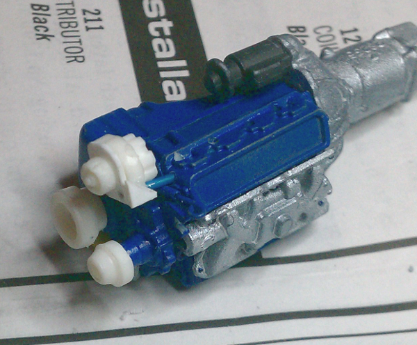
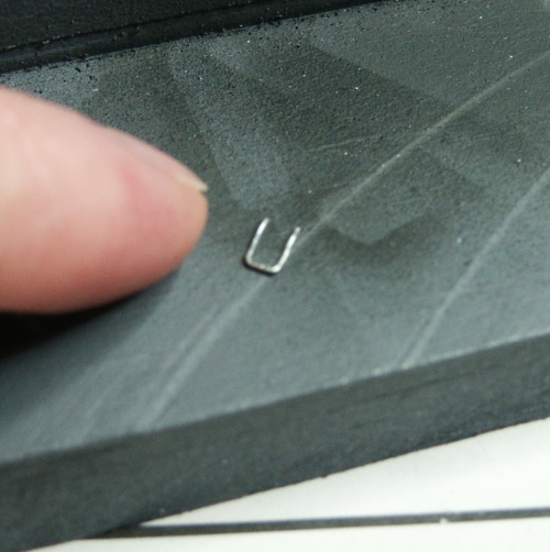
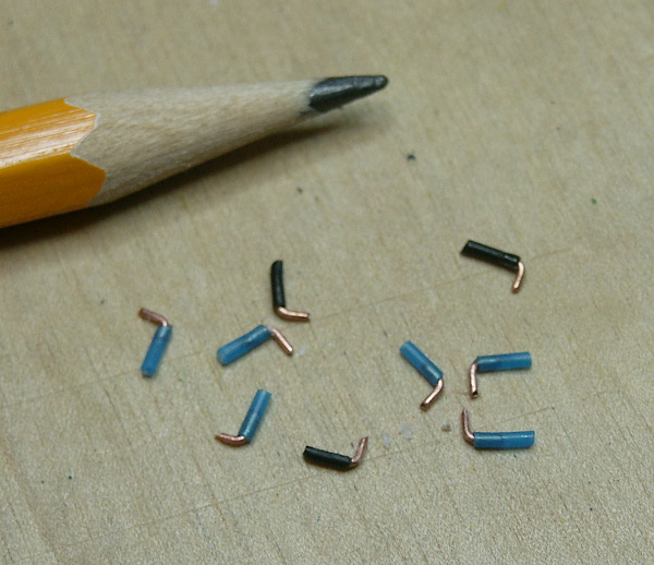
These are the little ignition wire guides, formed from 26 gauge steel wire. I drilled holes in the valve covers and sunk these in place. They are visible installed in the later pics.
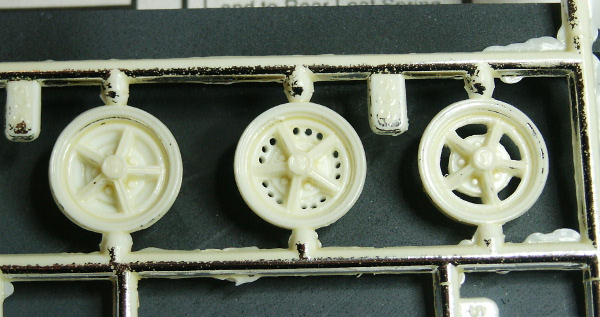
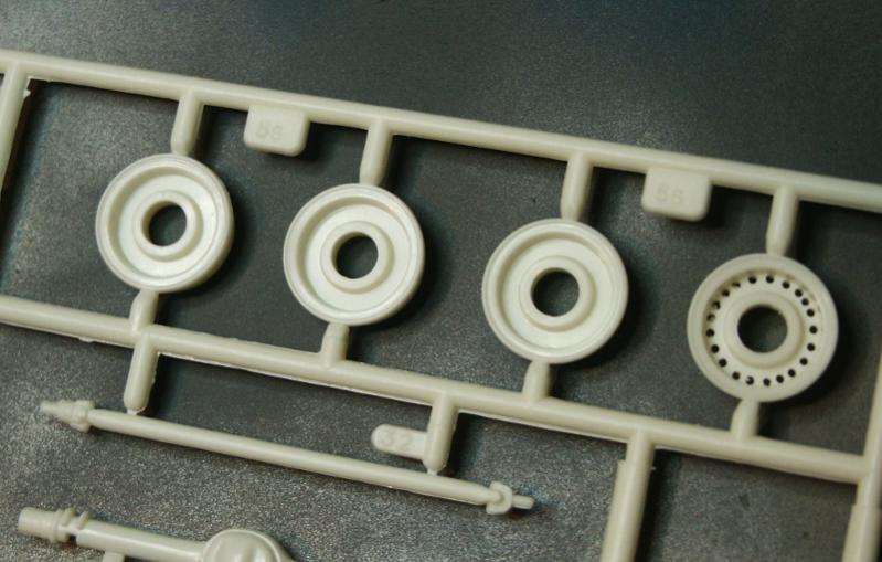
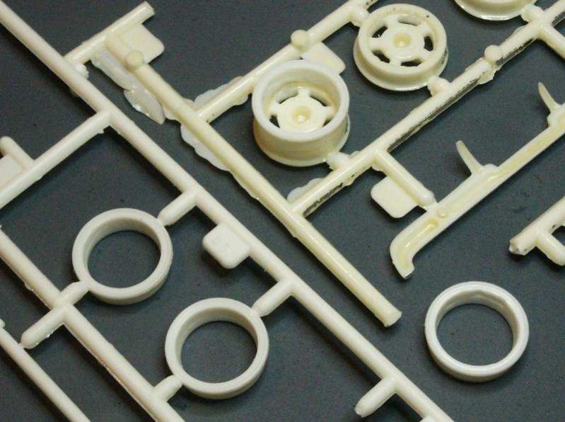
Some time clearing out the openings in the wheels. Drilled to remove material, then cleared. Sanding to come.
And shots of the engine with better depth of field. I also dusted with a paint brush, but I still see a few shards of plastic dust. You can see the plug boots glued in the holes, with 90 degree boots on the outside ends. These will be duplicated on the distributor, then have .010 steel wire glued into the boots and painted. Heater hoses are there, and the valve cover vent line.
-
23rd March 2014, 21:41
#7
Re: AMT Shelby GT350 build
A nice extra couple of hours today to do some airbrushing on the chassis.
First though, some pics catching up on other earlier progress.
The 90 degree angle ignition wire boots that will (hopefully) plug into the distributor:
I already posted the pic showing my trimming out the fronts of the mag wheels. Here, the solid rears are going to get cleaned out to match. I initially was going to hand drill all those tiny holes then clear the material with by hobby knife. But to save time, I borrowed the use of a Dremel, which only resulted in melting the plastic on it's lowest speed setting. So I borrowed the use of a drill press and a 1/2 inch bit at 750 rpm... Easy. You can see one test fitted to the front rim still on the tree.
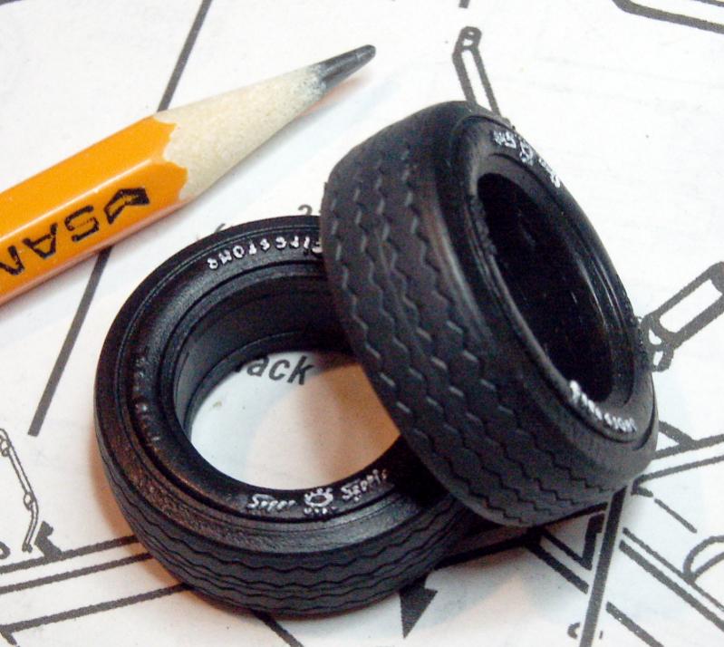
And here are the airbrushed tires. Treads were sanded by putting each tire on a shank on an electric drill, and running them on sandpaper. Black airbrushed on the sidewalls, dark gray treads. White letters were done with a tiny wood dowel.
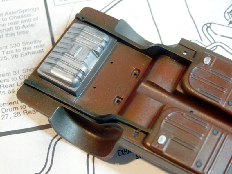
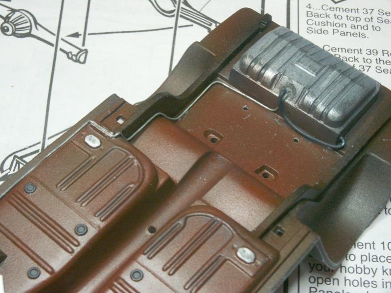
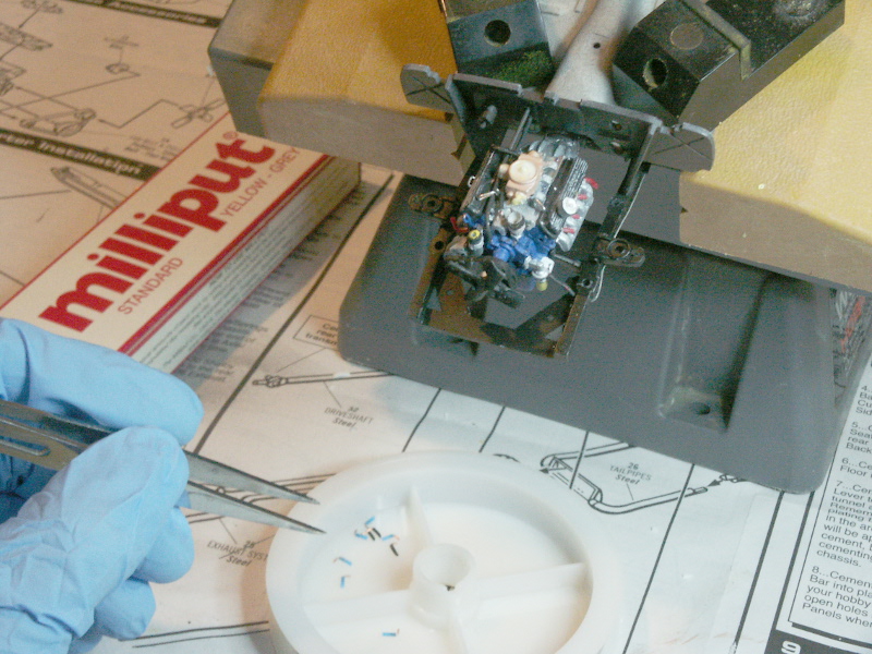
Finally, the chassis! The engine is getting too delicate to handle, and I still have more work to do on it. It looks like I can mount it in the chassis and complete my work from there with only minimal direct handling. I started by joining the firewall to the chassis pan.
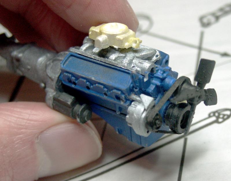
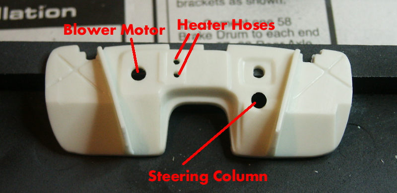
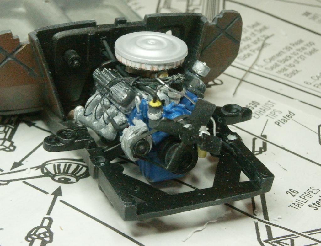
The firewall was missing some details. Namely, the heater hose holes and blower motor, as well as the steering column hole. The steering column isn't even included in the kit, I'll have to build one later. So I drilled the missing holes:
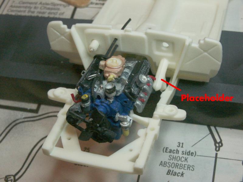
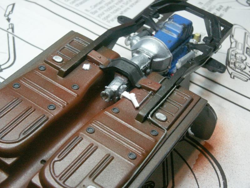
And a test fit. Note the blower motor (made from scrap sprue and wire) installed in the hole left of the engine. Placeholder sprue steering column sits in on the test.
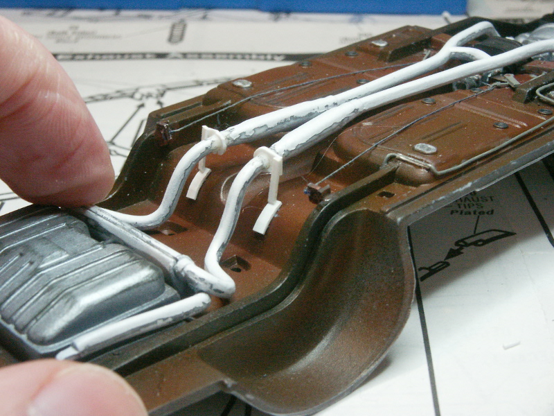
Also, notice there are now two tiny metal ignition wire guides sitting atop the manifold. These should help tame my wiring runs, and will be painted black with the wiring. These wire guides have a long tail, which were pushed down into holes in the manifold. Holes were created with a piece of the same wire heated in a candle and pushed through the plastic.
While I was at it, I noticed that the steering has all the pieces to allow the wheels to be posed left or right, but that they are just glued together. So I drilled out where necessary and will pin them together later (again, hopefully) allowing them to pose.
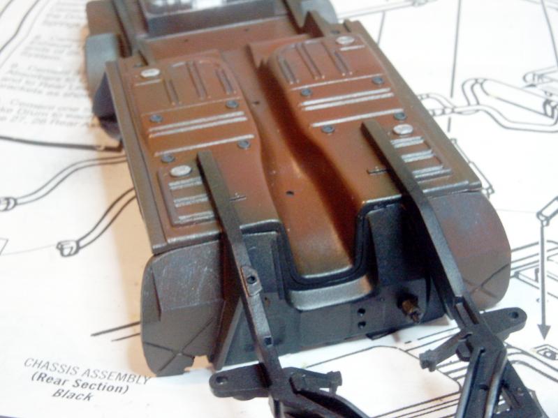
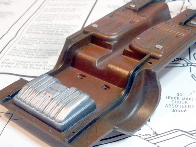
And now the chassis pan after airbrushing and some drybrushing. This went well. I've had a bit more practice and didn't have any issues with the paint "pooling" or running. I kept the air pressure as low as 6 or 7 PSI during the first "mist" coats, then up to maybe 10 PSI while putting down a more solid color.
-
26th March 2014, 04:22
#8
Re: AMT Shelby GT350 build
Big fun! What color will the body be?
FAST AND BULBOUS!
-
26th March 2014, 16:31
#9
Re: AMT Shelby GT350 build
Blowhard, I'm going to paint it in the red with white stripes and the parchment interior.
Another catch-up post:
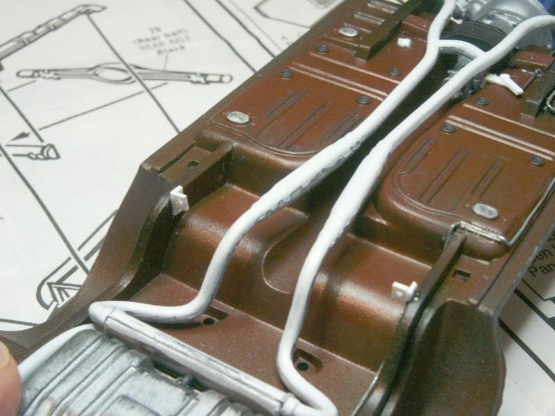
This evening I spent trying to model the fuel line and parking brake linkage.
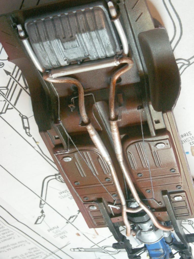
The fuel lines are wire that I bent to shape, and then tacked in place with CA glue. Note near the front of the chassis, where the fuel line begins its extension along the black painted frame member, there is a short black thickness along the line. This represents the rubber hose that joins the two piece steel lines on the 1967 car photos I based this on. Some apparently were solid lines, and it could be that some late 1967 (and apparently 1968 models), the fuel line didn't run along the outside of the underbody, but instead along inside the drive shaft tunnel.
The white parts along side the end of the transmission are the parking brake linkage, based on what my pics are showing. New hole in the firewall, and the cable comes down to the angled arm. Then fine wires will reach back from this linkage, on through the two small drilled holes in the brackets on the frame near the rear axle. Brackets are sheet styrene.
Engine is glued in place, but the exhaust system is only test fitted (and is still in need of some putty and sanding).
-
31st March 2014, 01:55
#10
Re: AMT Shelby GT350 build
Weekend update. Some little bits here and there, plus some preparation and planning for future work.
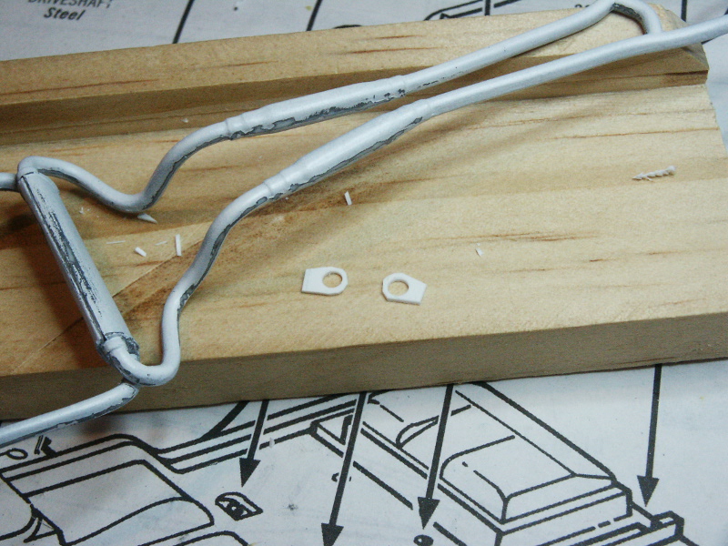
Up first, work on the exhaust system. Default kit had no hanger hardware modeled. I crafted these from sheet styrene for those shown in the pics below. The hangers for the tailpipes were crafted from wire.
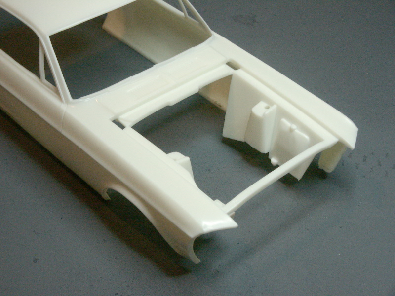
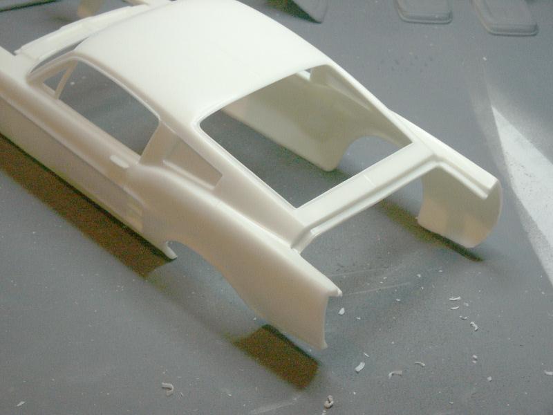
Next up, after test fitting the body to check a few clearance areas, I found the front fender wells being molded to the body was a huge pain. Having to "stretch" and manipulate this very tight fit in near the delicate engine details just didn't sit well with me. So I decided to cut the wells off the body molding. This will let me detail them better, too.
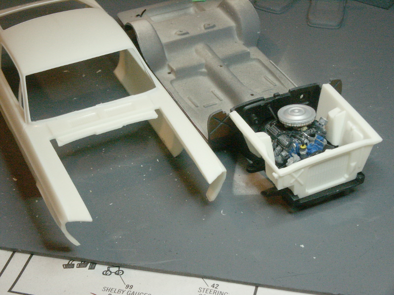
Test fitted wells on chassis, along with the separate radiator part.
Also cut the trunk opening out, so I can display it open if I wish.
And now after bits of airbrushing, drybrushing, some washes, and brush work. Note the late addition of the rear brake line coming down the drive shaft tunnel. You can see the completed parking brake linkages and cabling, too.
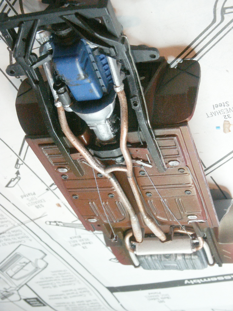
My prior plan to put the ignition wires into Milliput in the little distributor cup I made. This might have worked, but the scale effect was obviously wrong before I was half done. Scrapped the idea, and filled in the distributor solid with Milliput.
Ignition wires were glued direct to the distributor, and are inserted into each of the spark plug boots. Fuel line is installed, and the air filter sits in place for the photo.
Here is the scratch built steering column. After the fender wells are mounted, plus the power brake cylinder, this part will barely be visible.
Some primer and test fitting on the next parts of assembly.
 Posting Permissions
- You may not post new threads
- You may not post replies
- You may not post attachments
- You may not edit your posts
-
Forum Rules


 Reply With Quote