-
24th April 2014, 03:57
#21
Re: AMT Shelby GT350 build
Me too!!! 
 FAST AND BULBOUS!
-
28th April 2014, 01:32
#22
Re: AMT Shelby GT350 build
Well thanks, I am glad you guys are enjoying it.
I was working on little bits all over the model the past week. Most of these were done in little half-hour stints. Sorry for this huge post, it was longer than I expected.
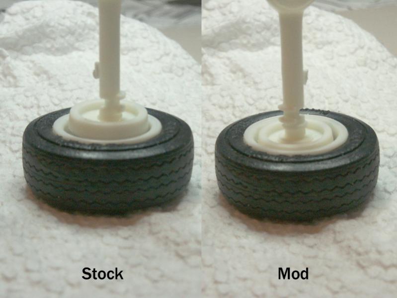
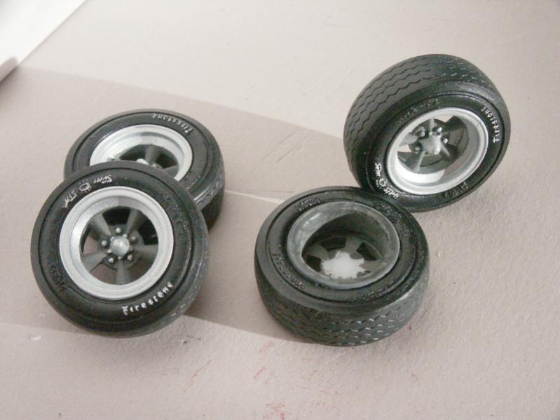
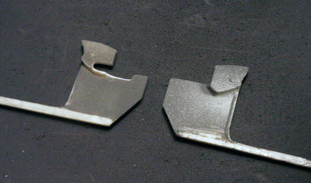
This is a comparison of the stock kit drum brake positioning (as best I could determine) and my modifications to get the drum inside the wheels.
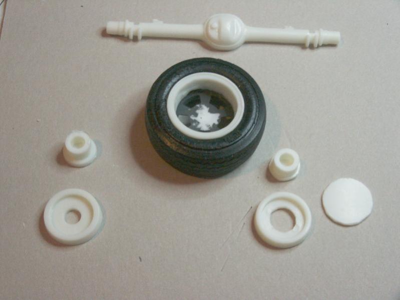
The parts... Left two are stock, right three are mod.
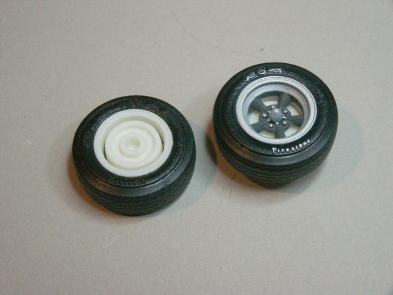
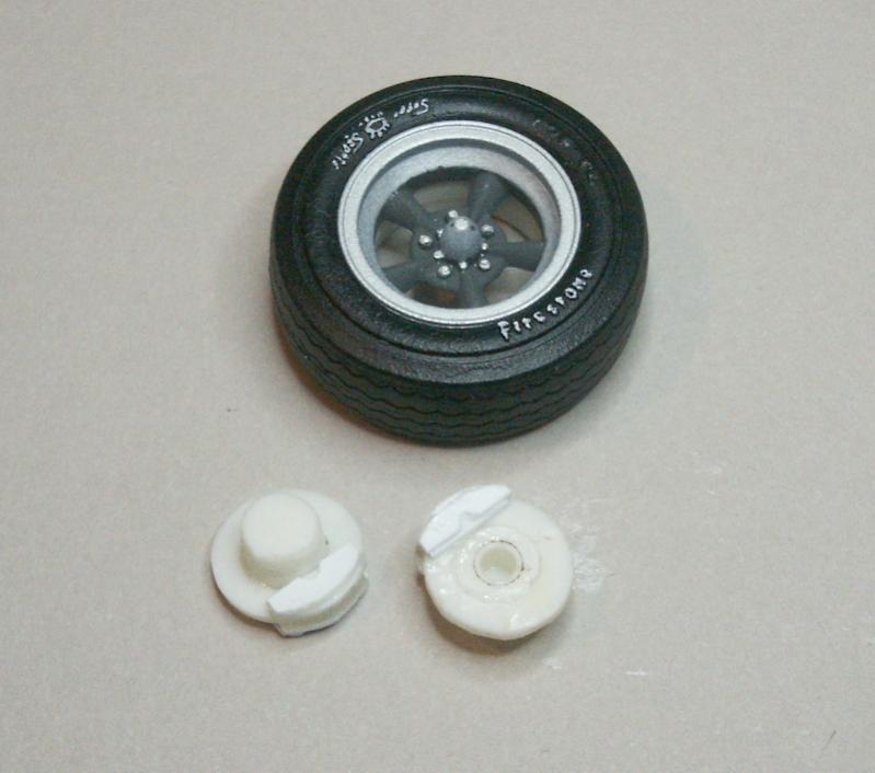
Finished product, also visible through the mag wheels.
The disc brakes also sat a bit inside, but worse had the caliper detail on just the inside. So I removed the calipers and recreated them. Drilled out the discs to fit them within the wheel a bit better, too.
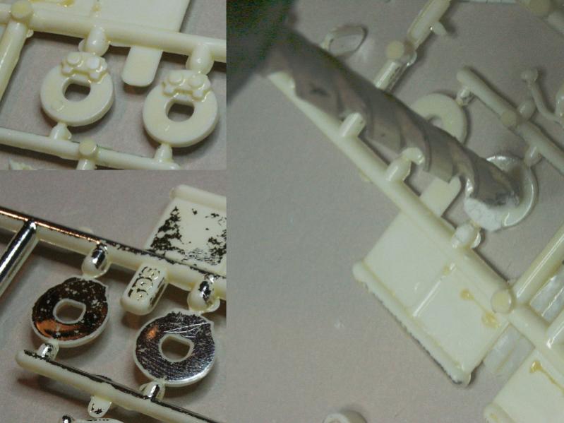
Final unsanded disc brakes.
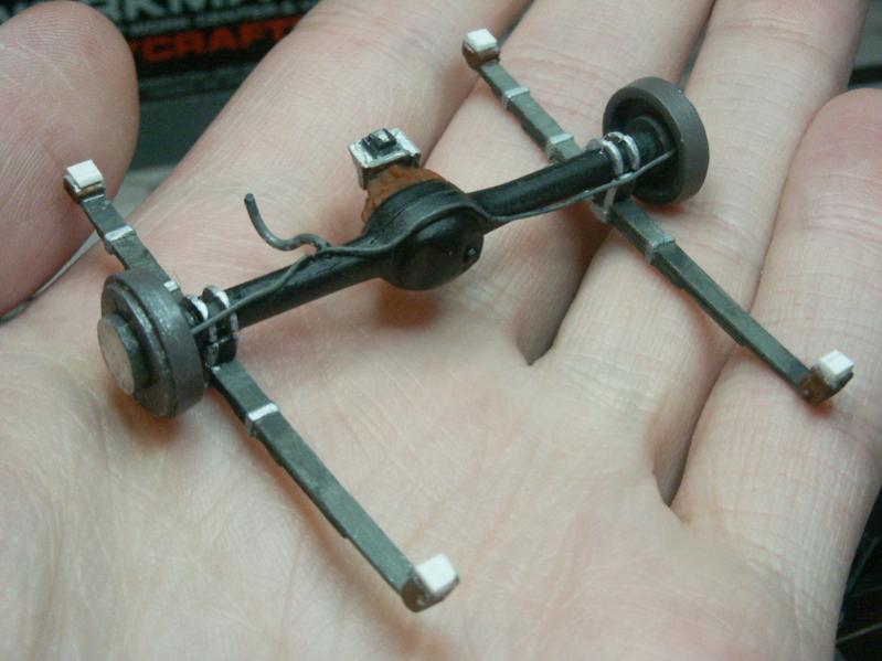
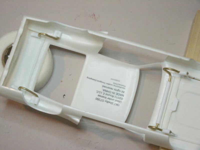
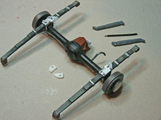
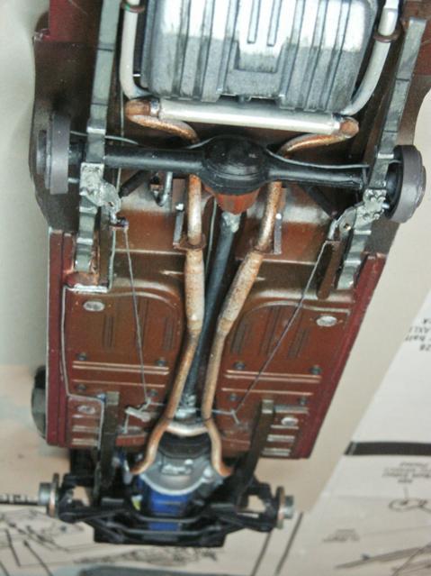
Rear suspension, showing brake lines and the scratch built "snubber" mount on the differential. Modified drum brakes are ready for the mags/tires to be superglued in place.
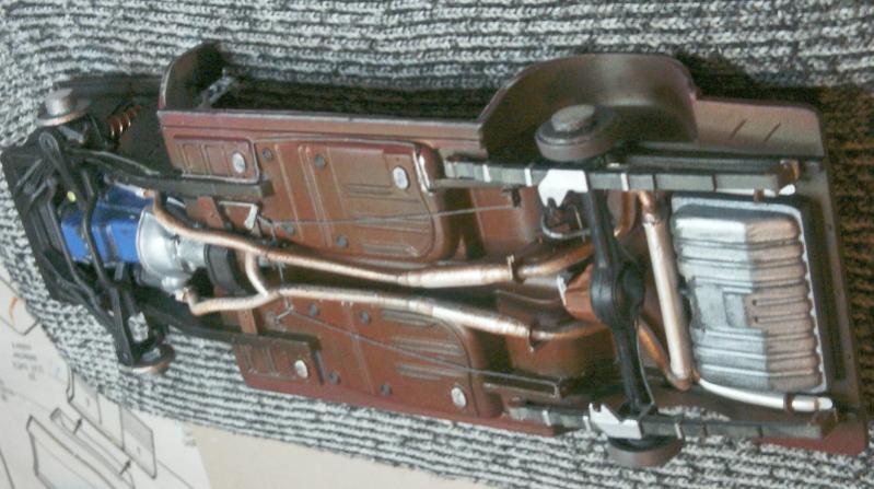
And the underbody with all the brake and suspension parts resting in place.

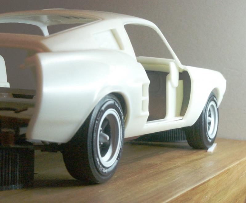
The same assembly flipped over (carefully, lol) and sitting up on bottle caps. The wheels are positioned as close to correct as I can get it for this test. I had to raise the rear suspension by .040" to get a good looking height, rear track was fine without a touch. Front track had to be narrowed by about 1/8th of an inch to get the wheels under the body!
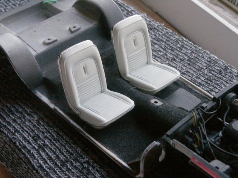
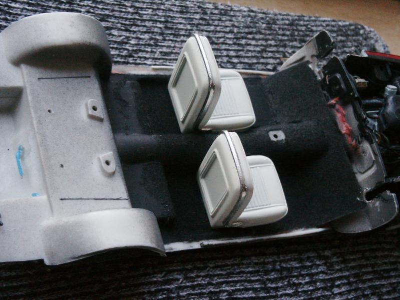
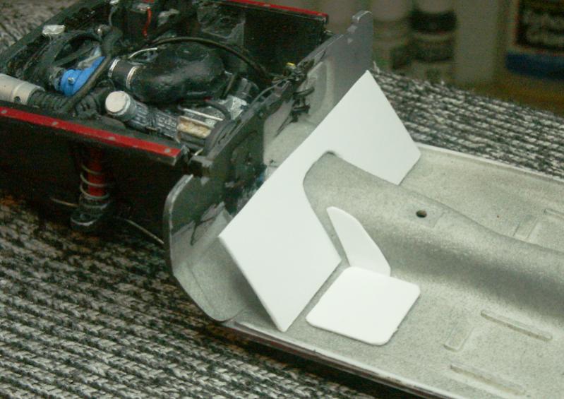
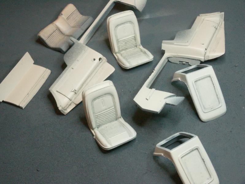
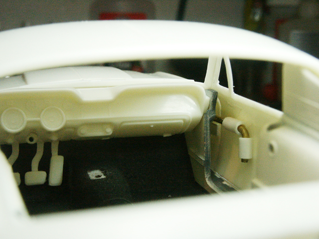
Preparing a bit for the interior flocking. Stock floorboard was way forward compared to photos.
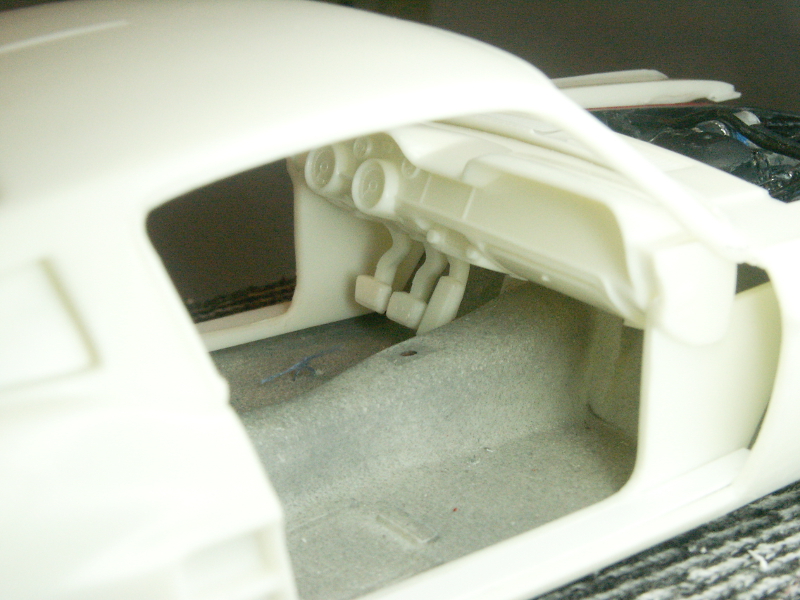
Also it had the squarish effect (actually the rear of the firewall molding) around the tunnel, also not apparent in photos.
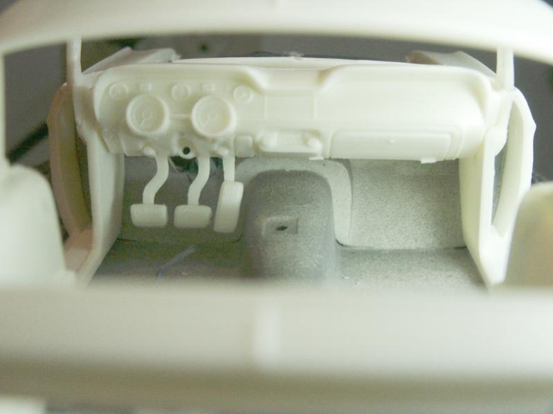
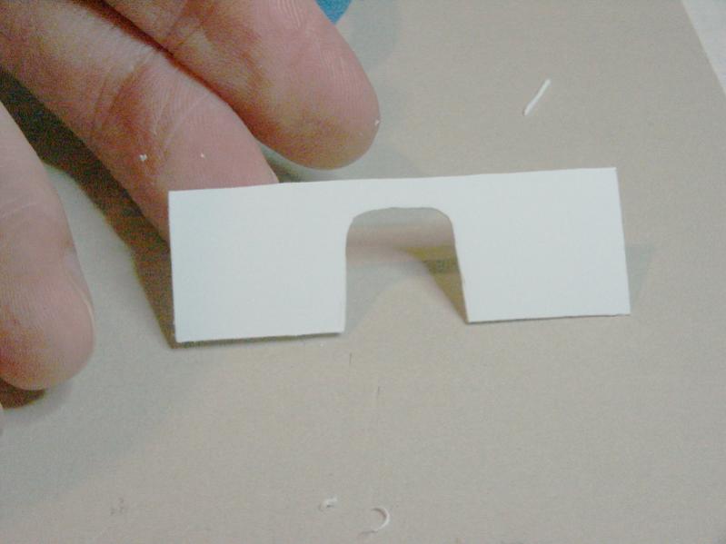
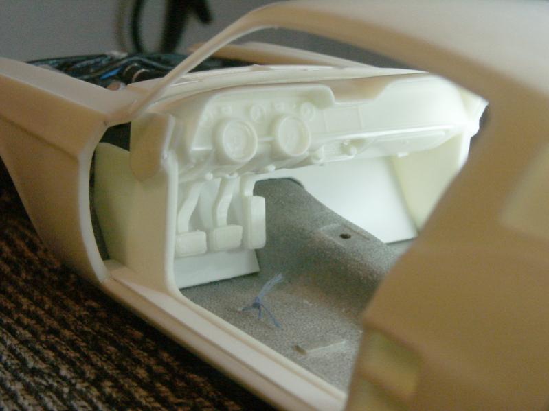
So I made a new sheet styrene floorboard. Photos below show it in place, but without the putty to blend the seam.
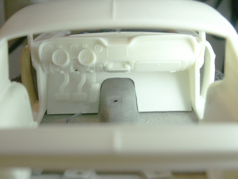
Reading suggests that those "GT350" floormats so often in photos didn't come along until the 1970s, and in fact the car didn't ship with any mats. Buyers could apparently option some stock Mustang mats if desired. I will simply model the basic mud guard which is part of the forward carpet section.
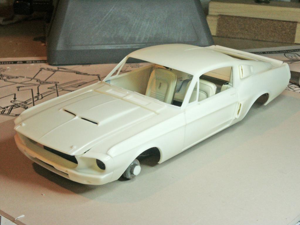
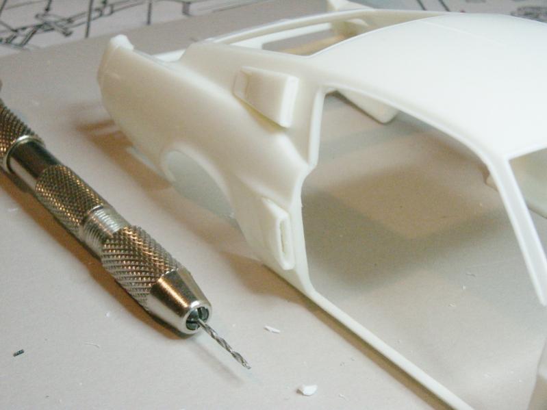
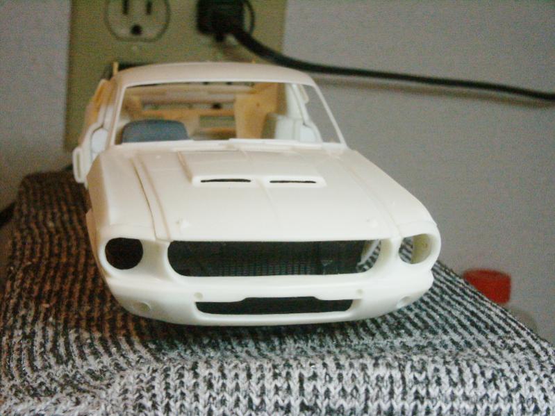
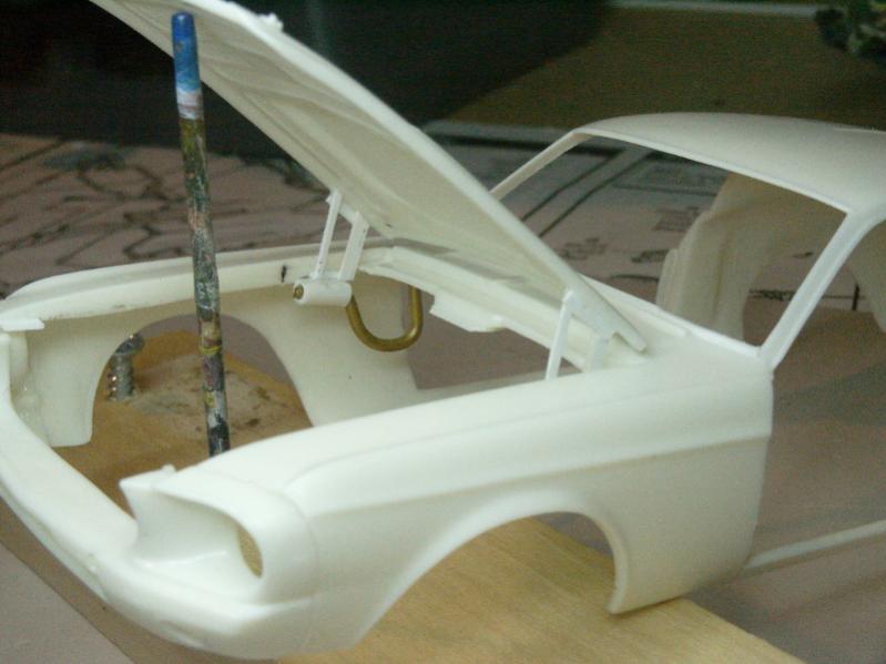
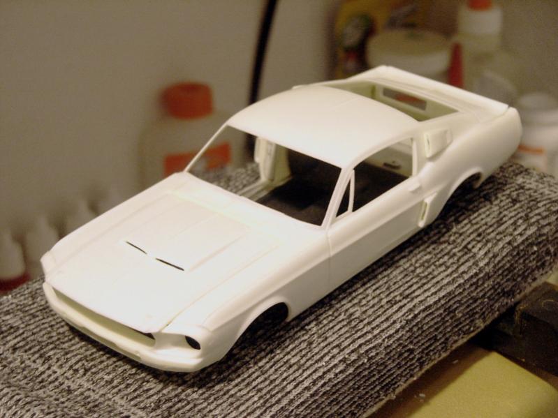
Working to drill out the body side air scoops.
Today I spent about 3 hours working on the hinging. Everything worked, but I am tired. The trunk was easy, just half an hour. But the hood... getting it integrated into the engine compartment section was incredibly slow and tedious. Not to mention risky with all those little parts jammed in there.
If there is a moral to this post, or indeed this entire thread... it should be:
HINGE BODY PANELS BEFORE DOING ANYTHING ELSE!
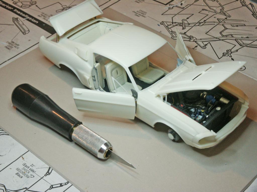
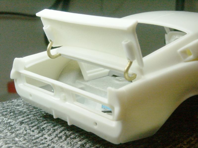
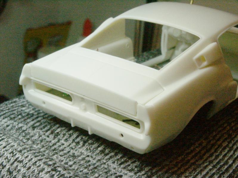
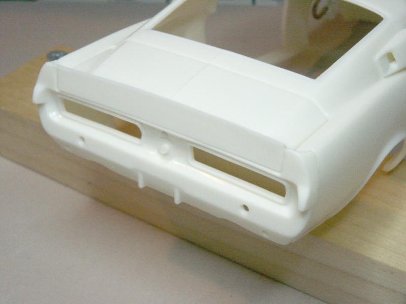
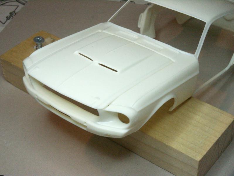
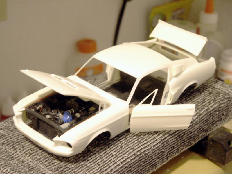
So here are the results. Trunk is fitted, but needs some minor tweaks. Hood is not done, I'm beat so I'll work on that later.
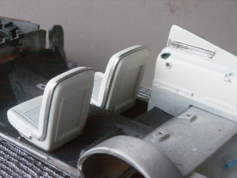
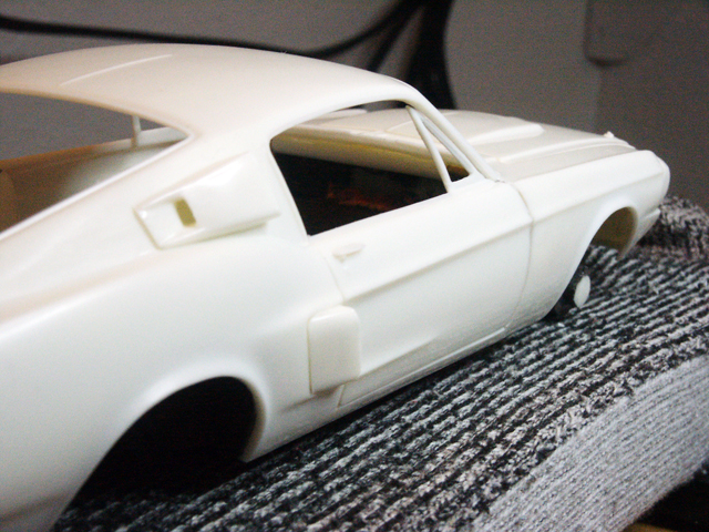
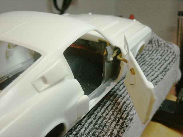
And a few other shots not included above. First, the finished air scoops, plus the door jambs made from sheet styrene. Seat sitting in place for reference.
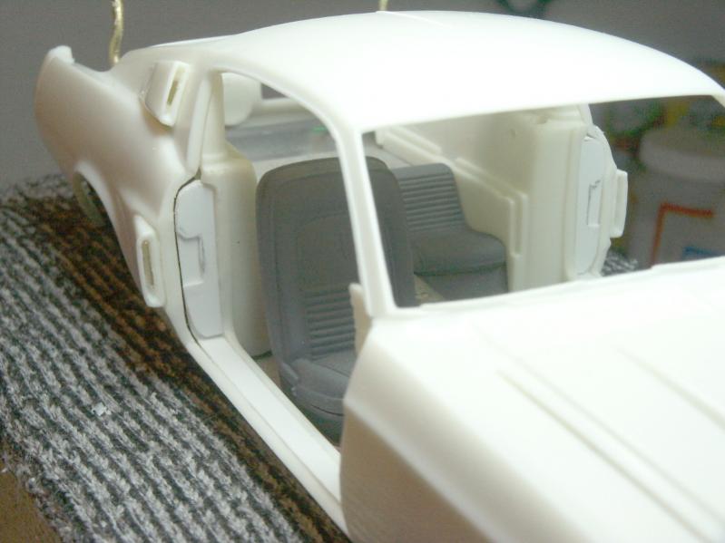
The front cowl had a poor fit as you may recall, but I did some scraping and it glued up pretty nicely and is ready for putty. Rear panel glued up very clean as shown above. Also opened up the hood scoops.
-
Re: AMT Shelby GT350 build
This past week, I have continued to work on hinging, and preparing the interior for near future assembly steps.
First, the flocking. I tried four (4) times to flock the interior, and each failed. I will spare you all the photos of disaster. Just imagine a clumpy, uneven mess, and you will get the pics.
First 2 attempts were following the several internet tutorials on flocking.
1) Apply a white glue/water mix with a brush.
2) Sprinkle flocking using a sifter.
3) Gently press the flocking into the glue.
4) Allow to dry a few minutes, tap away excess, or use a soft brush.
5) Gentle blast from a hair dryer to clear away final loose parts.
Then you are supposed to repeat to either fill in empty areas, or to gain thickness. I never attempted a second coat, as the first applications were such horrible results. Each time after about 30 minutes of drying, I simply peeled off the white glue film and it was un-done.
Attempt 3, I switched to the tutorials out there which recommend paint as the adhesive. I used some orange acrylic, of which I had a bunch with no plans to use it. (Remember, the colors don't matter as I intend to airbrush it to the correct color.) Same steps as above attempts. This time, I never even got to the hair dryer. The results were so clump and lumpy after tapping away the excess, it was obvious to pull the EJECT handle ASAP.
This was a big mess. Wet a cotton swap on a wooden stick and scrub. Repeat. Repeat. Complete waste of time.
Attempt 4 it was back to glue. What could be going wrong? Was I not pressing the flocking down gently enough? So I go through the steps again, with ever so light pressure to seat the flocking into the glue. And on the new forward floorboard, I just didn't press at all!
And when I tapped away, and later used the hair dryer, I could see it. Where I had NOT pressed, I had good, even coverage! Otherwise, the results were near the same as before. The quality result where I had not pressed was the answer, so again I stripped off all the flocking/glue.
So attempt 5... Zero pressing. Zero touching of the flocking at all, not even with the soft brush. Sift, and tap away the excess within 30 seconds or so. Success! It was thin, but clean and even. After it was dry several hours, I repeated again with zero touch and got a nice, even, and fuller coverage.
Again, dry thoroughly, and then airbrush. You can still see a bit of the orange remaining. It'll never show. I'm pleased with the result, but ouch on the time invested to get it. At least I learned how to do it!
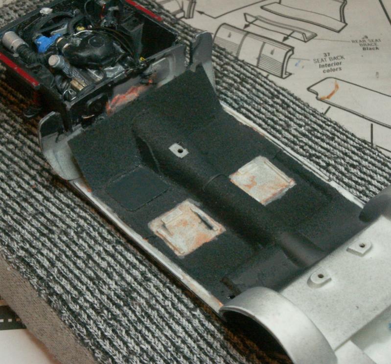
Also spent a bit of time doing some prep coats and washes on the "parchment" color interior parts.
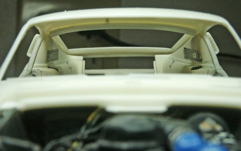
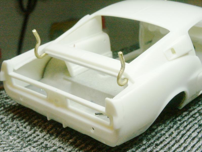
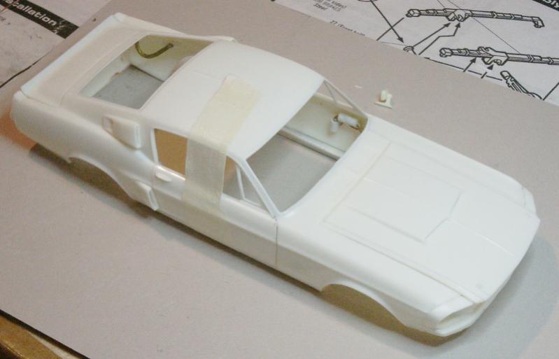
Next was another problem from last week. My hinging on the trunk impacted the body work on first open, and then was resting on the bodywork/rear window at full open. You can imagine the disaster for the paint later on. So I worked on the geometry problem a good while. The solution was in moving the pivot axis farther forward, to attain more lift during the opening arc.
This presented a new problem, however, as the hinge was as far forward as possible without clipping into the interior (and being visible through the rear window). So I had to use two separate hinges, each reaching outboard to the fenders, rather than a single piece hinge across the middle.
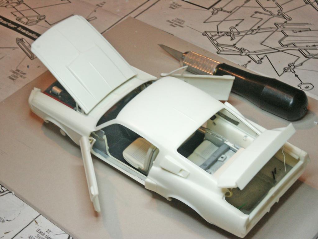
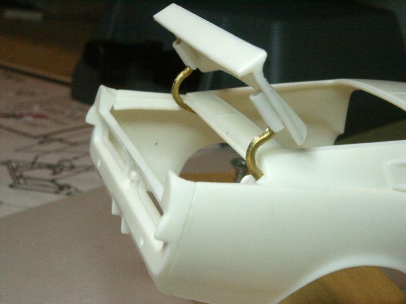
New hinge results:
Trunk lid doesn't impact the body, and lifts nicely at full open.
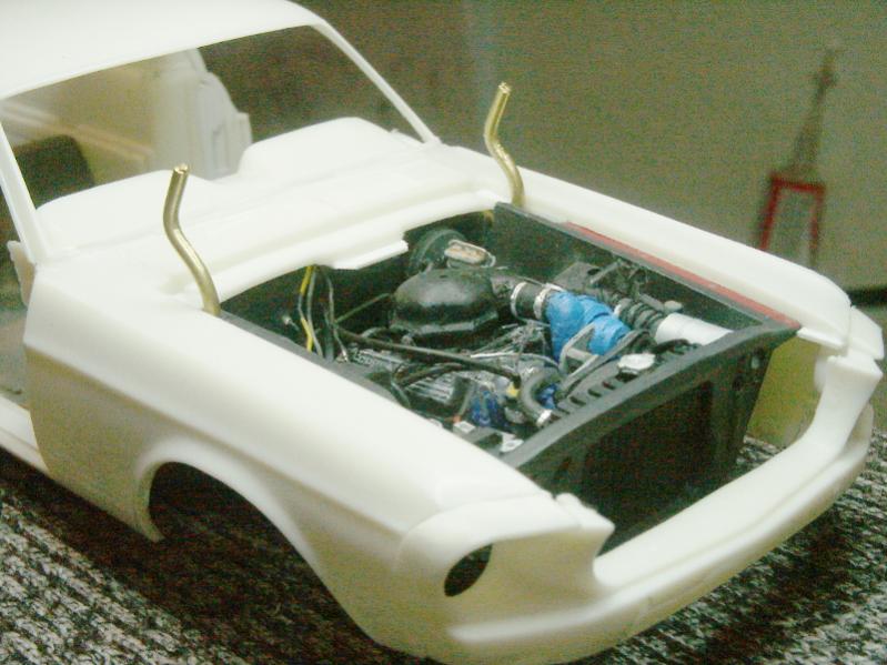
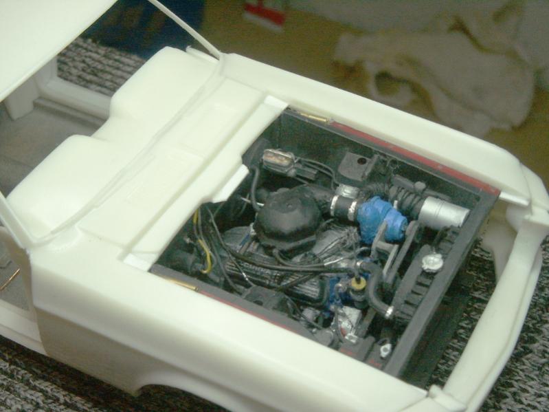
The hood pivot axis was OK, and when I got my styrene hood hinge details modeled, they worked fine.
These are made from styrene tubing and strip stock, to better model the real hinges. They are in the wrong place (rather than opening from within the engine compartment, they stow within the fender well area), but they look better IMO. The brass rod never is visible from under the hood, and retracts neatly behind the dashboard in the interior, out of sight.
Here you can see the new trunk hinge placement.
And I did a bit with my gloss and satin varnishes. Some under the hood (no good pic), and some on the wheels.
-
Re: AMT Shelby GT350 build
Amazing work!

-
Re: AMT Shelby GT350 build
EXCELLENT! Will you put little springs on your hood hinges?
FAST AND BULBOUS!
-
Re: AMT Shelby GT350 build
Yes, that's my plan. They'll likely be mounted statically, in the engine compartment. That way they'll be in the right place when the lid is open, and I'll have a chance to try to do something like integrate them into a simple latch for the holding the hood in the air.
-
Re: AMT Shelby GT350 build
The past week has been slowed by devoting full attention to the door hinging. To mount them, I taped the doors in place on the body, and then glue the hinge in position. Started with the drivers door, and had to do the process three times to get a positioning and wire bend that gave a square fit when closed, and a decently horizontal swing with minimal "droop" on open.
Incredibly slow and tedious. Once this is done, I'll need to open a small slot in the very forward most part of the interior sidewall panel (mostly hidden behind the dashboard end and bodywork) to allow for the hinge to clear when closed.
Oh, and my initial idea for having the doors open "correctly" so that the leading edge of the panel drops behind the bodywork (instead of swinging out) was abandoned. I did built and test mount one door using such a hinge. To get a good clearance, I would have needed to open up a considerable panel gap at the top-forward corner of the door panel. With the door open, it would look right. But closed, there would be a very significant "hole" that would, I feel, just be too large at 1/25th scale.
Passenger door is now drying.
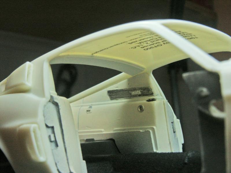
With the door hung, now I can begin looking at making the sheet styrene edges of the door, filling between the interior and exterior faces. Also opened up the little slot for the scratch built side windows to slide into. You can vaguely see the step-back just rear of the wing window base.
Last edited by adlabs6; 11th May 2014 at 21:19.
-
Re: AMT Shelby GT350 build
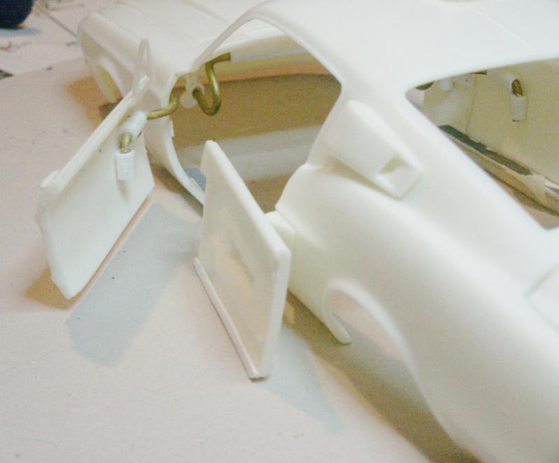
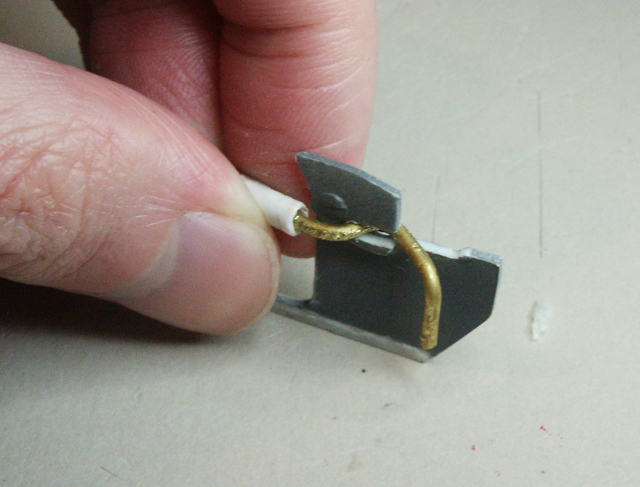
More work on integrating the door hinges as cleanly as I can with the interior. Bunches of test fits revealed that my door hinge shape would poke considerably into the interior, way too far. Thinking for a few days on the geometry of the hinge wire, I realized I could reduce this intrusion by steepening the bend of the wire, similar to how my trunk hinges are bent.
So I cut off the passenger door hinge (yet again!) and did a test bend/fit. You can see the difference below compared to the original hinge (still glued to the drivers door):
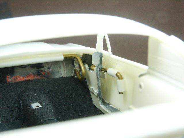
Looking at the interior panel, you can see the slot I had to cut to allow the wire clearance to close. If I had not reshaped the wire, that slot would have gone all the way through the part, lopping off the upper part of the panel. Since that panel is key to alignment of the dashboard, and plainly visible from the exterior when the door is open, I can't chop it off.
Here's the new wire fit in the slot, for clarity.
So again, glue and dry. Door closed, good alignment.
Interior with door closed, nice fit into the panel slot.
With the dash sitting in place, the hinge will be invisible. Before the rework, the hinge may well have extended through the front of the dash! 
And from the outside, the appearance is not too bad. Saving the top of that panel is a big help for scale appearance. Next week, same thing on the driver side door.
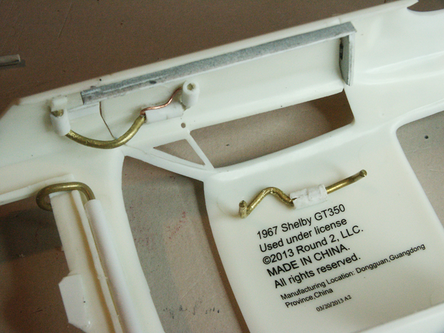
I also worked to finish up some suspension details. Firstly, the rear shock mounts were bothering me. Take a look at this pic from an earlier post, and notice the rear shock mounts are flat, smooth, and have a "C" shaped socket to hold the end of the shock:
Looking at photos, it would appear the real car has an angled section which holds the end of the shock. So I cut off the flat part of the plate and made some replacements from styrene.
Here they are glued in place. This mod made the shocks too short, so I cut off the end and drilled them out. Glue in a short length of wire that will pass through the hole in the angled plate.
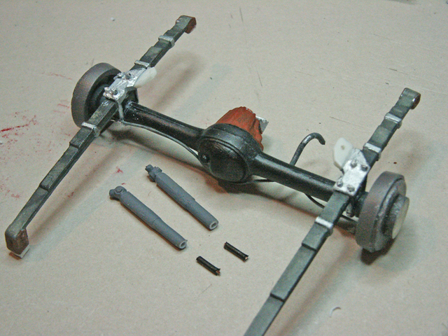
Near complete test fitting. New shock mounts are done, also note the bolts added on the flat part of the plate. Rear axle is pretty well adjusted for position. Shocks fit fine. Drive shaft is painted and glued to the differential. Final length of parking brake cable are in place at the brake drum.
Almost ready for final gluing and "painting-in"!
-
-
 Posting Permissions
- You may not post new threads
- You may not post replies
- You may not post attachments
- You may not edit your posts
-
Forum Rules


 Reply With Quote